Satellite Antenna Pads As Solid as Rock
Part III

It Takes Teamwork.
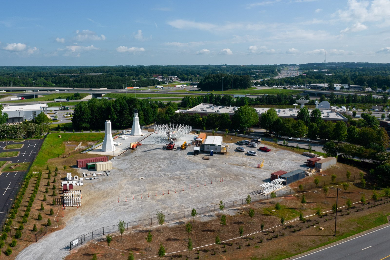
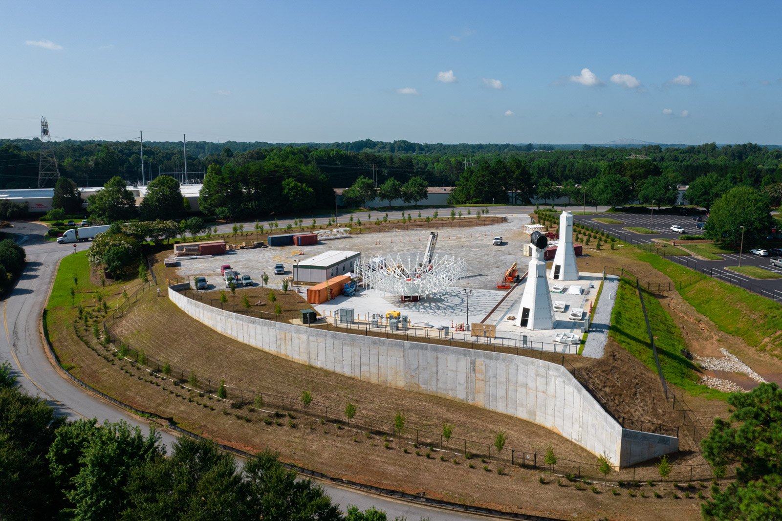
The goal of this project was to deliver an antenna test site to a high value telecommunications client. Efficiency and attention to detail were at the utmost importance while delivering this project and continuing success throughout the variables presented from the project. This project presented a lot of earth work and concrete work to be performed. It was a combined effort from Duffey and our trade partners in order to achieve a successful end result.
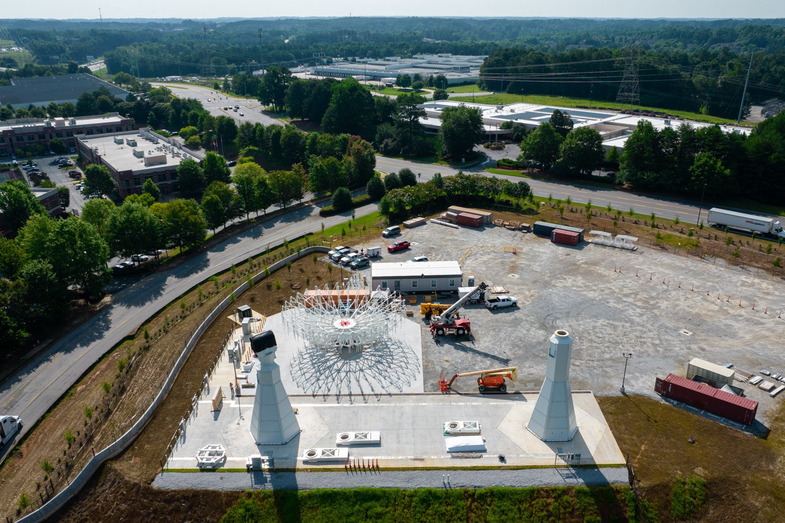
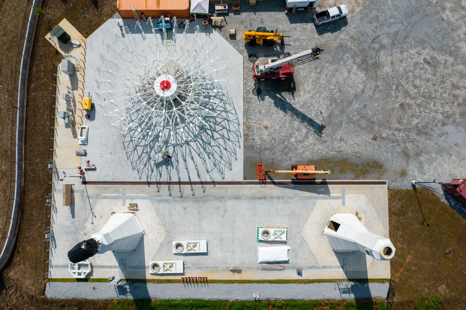
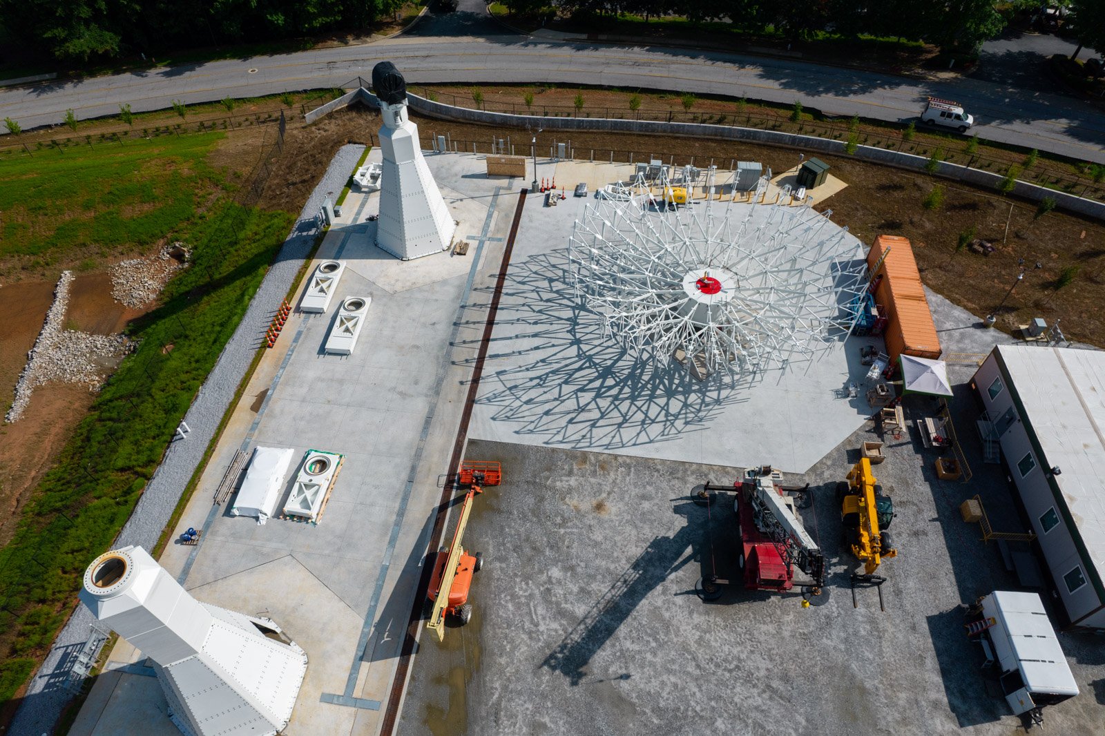
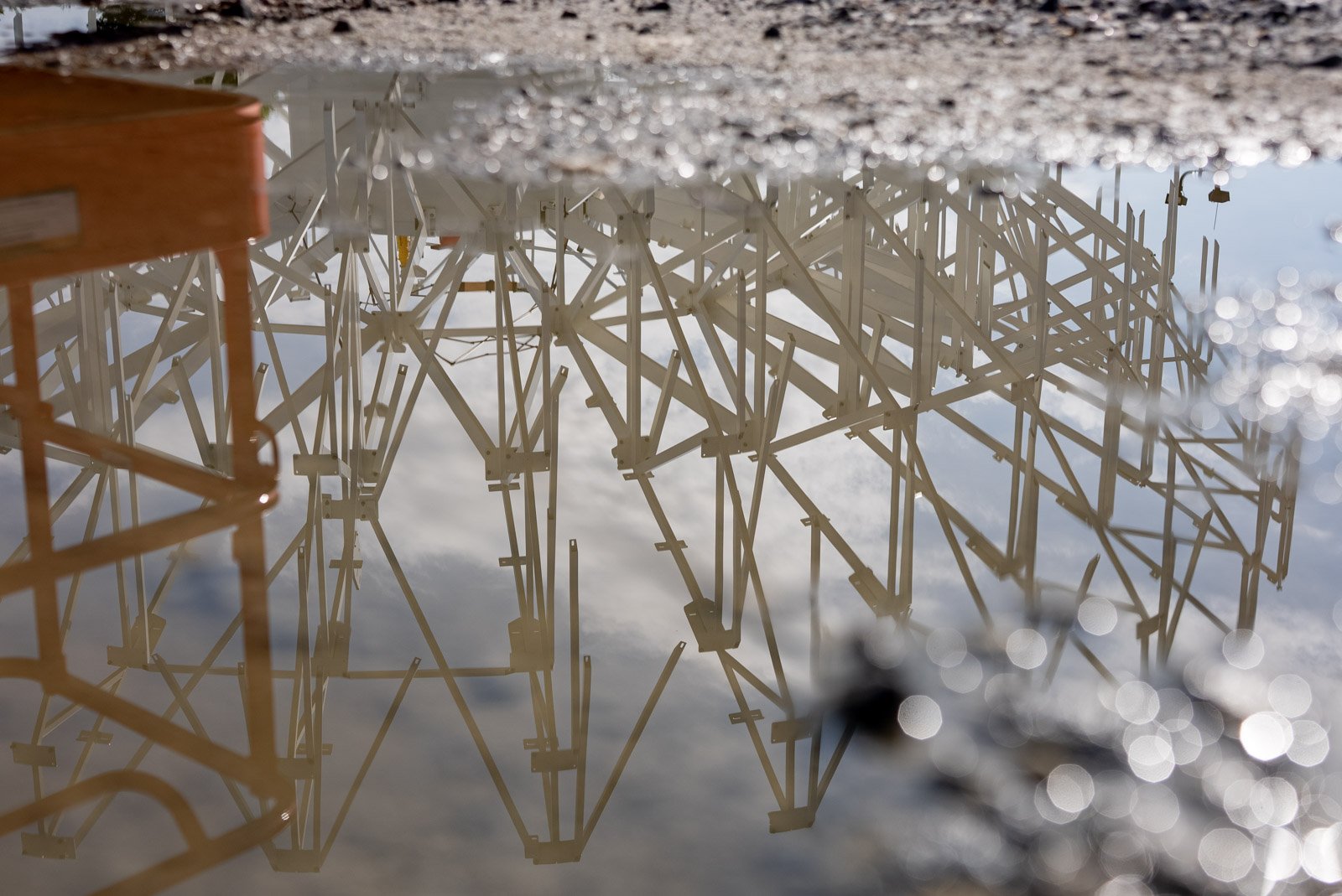
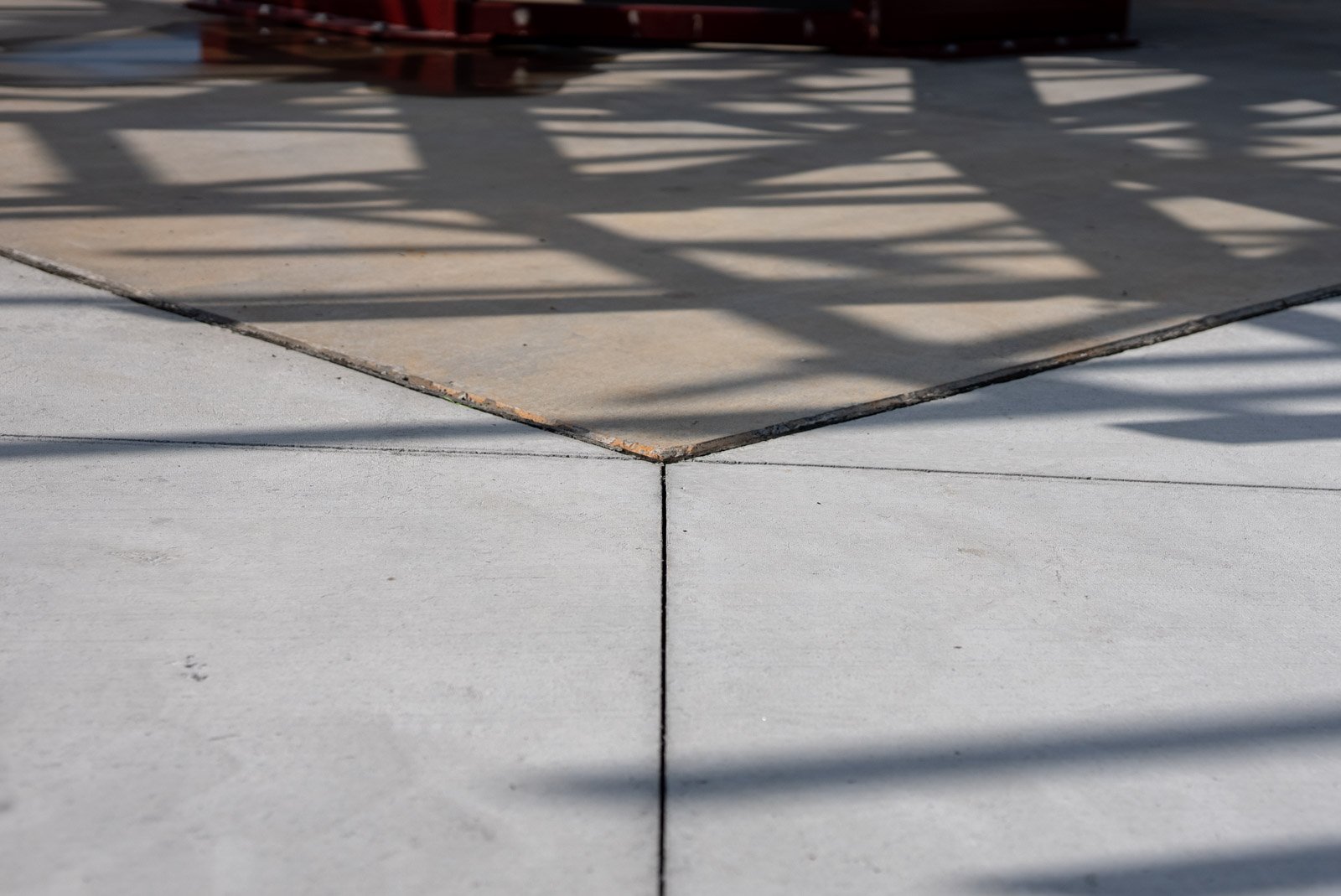
Our assembly pad is the SOG that was built to give the client a separate area to construct the antenna reflector while also stacking the antenna teepee. This allows the client increased throughput while antenna assembly operations are in progress. The assembly pad is composed of 2’-6” concrete depth with a rebar reinforcing matting to help the overall strength of the assembly pad. The assembly pad has an embed layout to allow the client to attach the reflector frame to the embeds and bolt the assembly in place while assembling the reflector. Once the reflector is built a crane will then erect the reflector to the teepee assembly.
A Massive Counter- weight
The amount of strength that was constructed within these foundations is very intense to allow the antenna operations to have a total infrastructure capable of maintaining the intended loads forcing through the foundations.
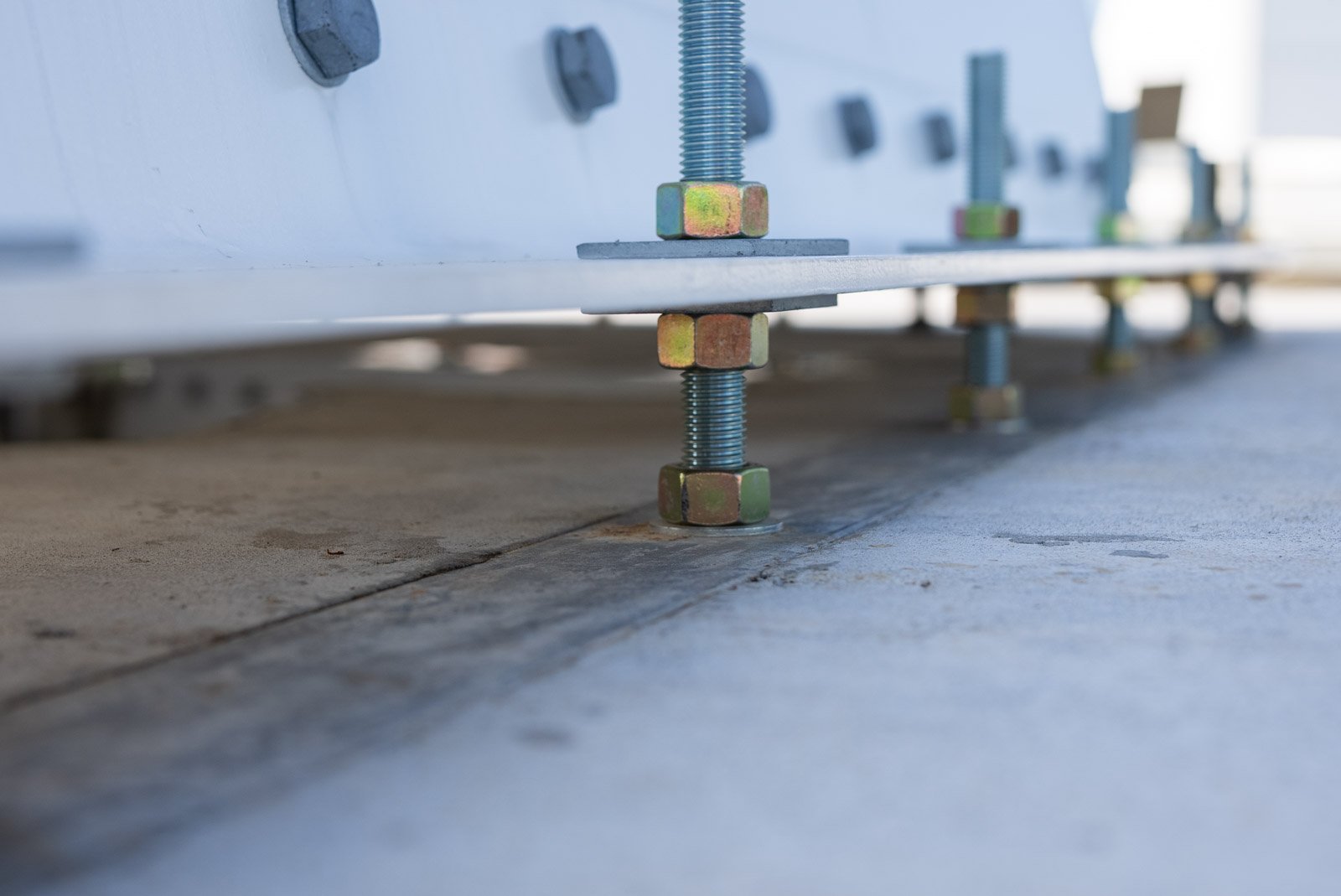
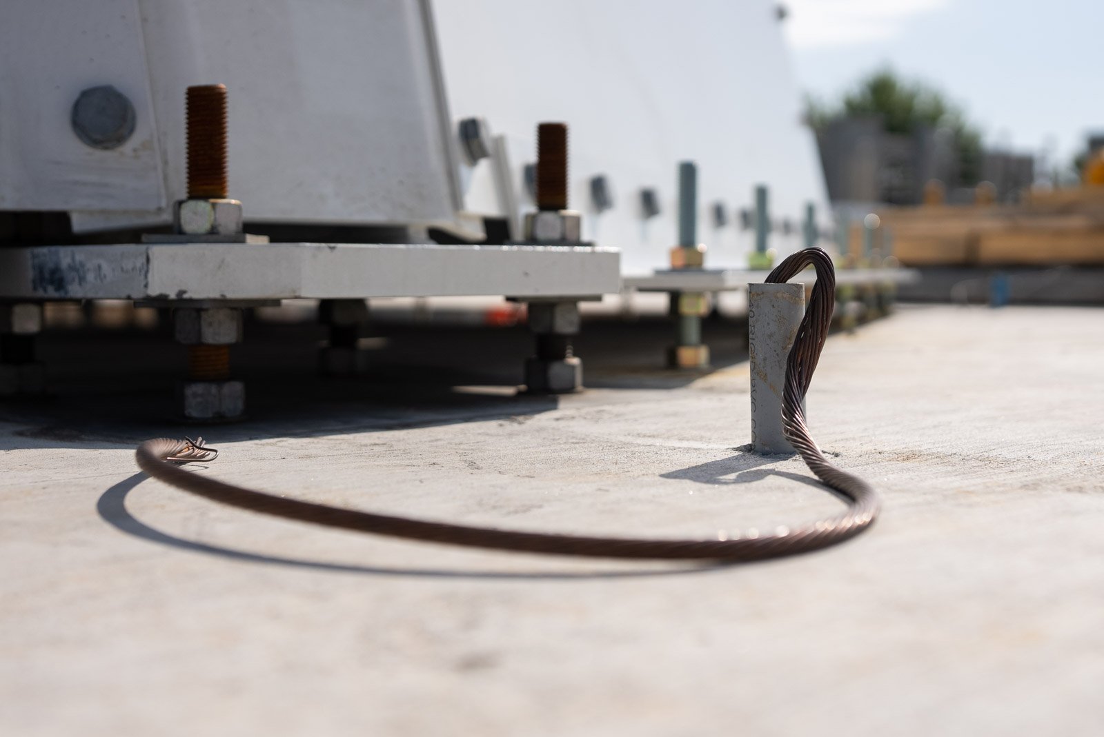
Our antenna foundation that was previously placed is now cured and stacked to accommodate the smaller of the two intended antenna systems for this site. The embed system that is used here creates a connection point for the based plates of the antenna teepee to attach to the foundation. Ultimately, this foundation is a massive counterweight to keep the antenna from tipping over and keeping the connection grounded.
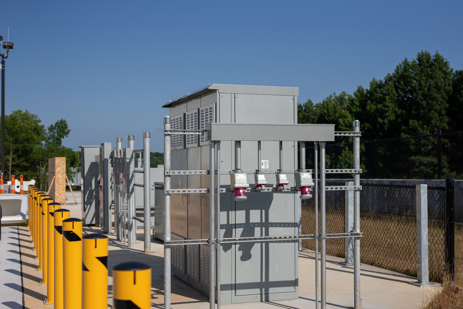
The electrical system used to support these antenna systems are medium voltage power distribution system which gives the antenna systems the specific power requirements needed to operate. Each electrical system was designed specifically for each individual antenna system.
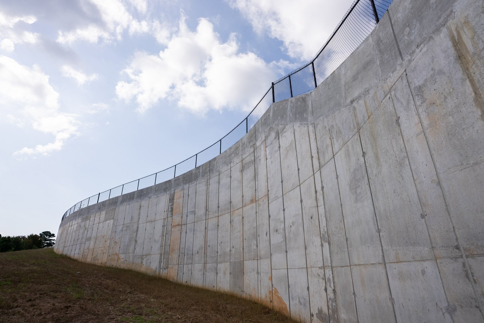
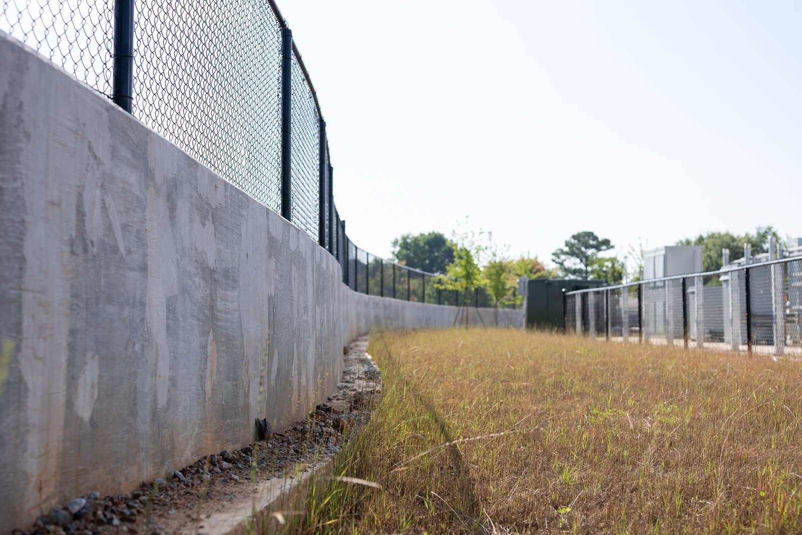
326’ Long and 35’ High Retaining Walls.
In order to bring the site to grade the design called for a retaining wall to be constructed. This retaining wall is 326’ long and 35’ high at the highest elevation. Roughly 2000 yards of concrete went into the placement of this wall. Without the construction of the wall, the site would not have been able to support the final grade requirements and meet the compaction densities needed to support the antenna foundations.
Delivery of this site to the client came with a lot of communication and scheduling, not only from Duffey but from our trade partners as well. These efforts really pay off when you come back to the site and see what you’ve built has come to life and the end user is getting the benefits of what you have built for them.